ROOTECH SERVICES is team of well Qualified, Experienced & dedicated engineers committed to give best quality of maintenance our products supported by prompt after sales service.Our goal is to provide advanced technology to meet our customers needs.py Profile We guarantee to provide the blowers with top quality and competitive price to our customers.
How to Select the Proper Root Blower and Data Required for Ordering
speify your usage, loacation and running continuous or intermittent
Provide the range of variation and specify whether the pressure specified is the static pressure at the outlet or the differential pressure between the inlet and outlet. Specify whether the inlet pressure is at 1Atm. If not, the differential pressure between the inlet and outlet should be provided.
Specify the required air-capacity is based on the standared conditions (1 Atm., 20 C,relative humidity 65%) or on the referential conditions. Unless otherwise specified , air-capacity is indicated in the intel conditions rather than the outlet conditions.
Please specify whether the pressure is constant or variant case, please specify the corresponding relationship between the air-capacity and pressure, such as air-capacity increases when the pressure decreases , and vice versa.
Please Specify the Following items:
Ordinary air shall be used if none the above items is provided.
The standard ROOTECH Blower is for transporting a gas of normal inlet . If the inlet tempreature is high , the rotor of the blower may seize due to thermak expansion. Let in corporate special design for the high-temperature conditions.
For a motor driven unit, please advise the voltage , frequency , phase , etc of your
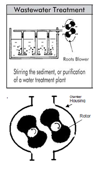
The Root Blower, is a displacement-discharge blower as well as a suction type vacuum pump. The unit uses 2 rotors, in the shape of, rotating in opposite directions, for compressing or extracting the air. Both rotors are connected to a synchronized gear set. While rotating, the rotor-to-rotor and rotor-to-chamber gaps are maintained fractions of millimeters; therefore no lubrication is required, thus delivering non-contaminated air.
Because there is no friction between the moving parts, the Root Blower allows high-speed rotation for giving out high flow-rates. Rootech root blowers are precision designed; only the bearings and gears inside the machine require lubrication. Please follow the timing for lubrication and select proper lube oil and grease as instructed by the manual. Proper maintenance can minimize wear and tear of the bearings and gears, so as to prolong the life span of the machine.
DESIGN FOR COMPRESSED TRANSPORT
A sound and level foundation helps smooth operation of the Root Blower; it also minimizes the maintenance cost and prolongs the life span of the blower.
Concrete Foundation
A concrete foundation is the best choice for the Root Blower. The mass of a concrete plinth shall be at least 3 times that of the supported machine; it functions as an inertia counter weight that stabilizes the foundation. In case the soil of the location is soft and lacks supporting force, a bigger foundation supported foundation shall be provided. For installation of more than 2 Root Blowers, foundations shall be provided. For preventing transmission of vibration, a plinth shall avoid connecting with the foundation of the building, a column, or a wall.
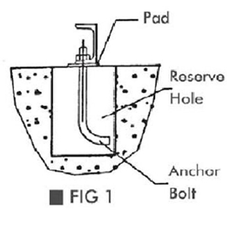
Holes for accommodating anchor bolts shall be prepared in advance. Embed the anchor bolts after layout of the Root Blower.
Embeded Anchor Bolt Foundation me t h o d illustrated in Fig.3 to place the L-shape anchor bolt into a pipe with a diameter larger than that of the anchor bolt by approximately 50mm, so that the bolt allows for slight adjustment after pouring concrete, if required.
The best ratio of the aggregates, in volume, shall be cement: sand: gravel = 1:2:4. The machine shall only be installed when the foundation is fully cured.
Steel Structure Base
Using steel structure as the base for a Root Blower (see Fig. 4), it is necessary to consider the strength and rigidity for maintaining the base from deformation under the expected load, which include the static and dynamic loads of the Root Blower and its accessories. The base must be sufficiently so as to prevent loosening resulting from the operation.
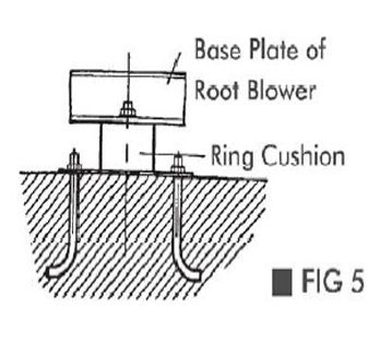
Installation of Vibration Pad (optional).
To prevent vibration induced by other equipment influencing the Root Blower, or to prevent vibration of the Root Blower from influencing other equipment, the vibration pad(s) can be installed between the base plate of the unit and the foundation. The company offers 2 options of vibration pads for being used with a Root Blower.
Precautions for Handling the Unit
When handling the Root Blower, avoid damage caused by swing or collision. Upon delivery check if all the accessories are intact. The following are some of things to check:
Check if the specifications of the unit are consistent with the order sheet.
Check if the any of the screws on the machine are loose due to the shipment or any collision.
Turn the shaft with your hand; ensure that the shaft has not been stuck.
When hoisting, use the ring-head bolt supplied with the Root Blower. Do not use the shaft end as a support for hoisting.
Installation and Adjustment
Before installing the Root Blower onto the foundation, make sure the surface of the foundation is free of oil or grease, so as to provide good contact between the base plate and the concrete foundation.
Keep the inlet/outlet flanges of the Root Blower sealed until connecting with the piping, for preventing any foreign object from entering.
After placing the Root Blower onto the foundation, shim the base plate at positions the main load is supported (insert the shim into the gap between the base plate and the foundation, aside the anchor bolt), leave a space for grouting the mortar. Finally, use shims (or wedges) to level the unit; measure the level on a machined surface. Maximum tolerance is 0.2 mm/m.
In case an old cement plinth is used, chip off the upper-face of the plinth, install the unit upon the newly formed surface.
Reserve a space for maintenance at the installation site, for facilitating future maintenance.
It shall be considered that the inlet of the Root Blower shall be situated at a location where good ventilation and clean air are available.
If the equipment room for the Root Blower is small, the temperature in the room is prone to rise up. A temperature higher than 40°C is adverse to the life span of the Root Blower, in such cases, provide a ventilation fan for heat dissipation.
Piping
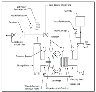
For ensuring smooth operation of the Root Blower, make sure the following points are taken care of when installing the piping. Clean out any slugs from the piping thoroughly before connecting the Root Blower. If a slug enters into the blower, severe damage can result. Avoid deformation of the Root Blower caused by connection with the piping; make sure the piping does not exert the direct load onto the Root Blower. Proper supporting is required in the vicinity of the inlet and outlet of the unit. Metal hangers or support can be used, preferably flexible ones. Make sure the centerline of the piping aligns with that of the unit inlet/outlet; do not force the connection. If applicable, use flexible joints to minimize the stress and strain upon the unit caused by minor Defections resulting from change of temperature. A check valve behind the flexible joint can prevent the Root Blower from water invasion caused by reverse flow. Mind the direction of the check valve. In case the inlet of the Root Blower opens to the atmosphere, a filter shall be provided for preventing sucking in foreign objects. Provide a rain shield for outdoor installation. Furnish silencers on the inlet, outlet, or within the piping, for eliminating the operation noise. If the transferred gas contains vapor, it may condense to water during the transfer; provide a drain cock at the lowest point of the piping system Keep the inlet filter clean all the time. Perform regular inspection and maintenance every 3 months.
Checking the Parallel
Make sure the pulleys are at their correct positions.
By way of a ruler or a straight line across the body and the pulley end, check that the end faces of the belt are on the same plane; check that the motor shaft is parallel with the blower shaft; and the v-belt pulley is at the right angle with the shaft. In case of any deflection, loosen the anchor bolts of the motor base for adjustment; tighten the bolts after adjustment is made. Before operating the Root Blower at full speed, check the direction of rotation first.
Belt Tension Adjustment
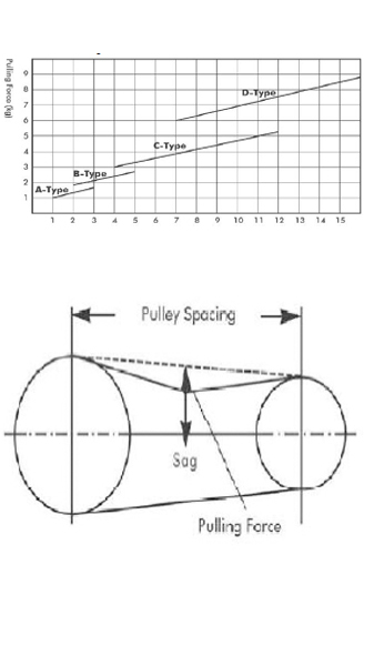
The optimal tension adjustment of the belt is to achieve the minimal tension at which the belt will not slip in the maximum load conditions (horsepower). Make several checks of the belt tension for any variation on the first day a new belt is used. Adjust the belt so it will not slip. After certain stretching, the belt tends to settle in its extension. After that, only occasional checks are required. In a multi-belt case, make sure all the belts are of the same length; they shall replaced together at the same time too. Keep the belt clean from dust and foreign materials, and avoid corrosion by gasoline or other oils. Check belt tension with the following methods: Hold the belt with you fingers and twist the belt; it shall be able to twist the belt 90 degrees. Or press the belt with your thumb; it shall be able to produce a sag of 1 thickness of the belt. After running starts, if a slip is heard, increase the tension a little. Increase the tension a little for a new belt. Tension can be calculated as follows:
Measure the distance between the shafts
Find the transmission power of each of the belts.
Pull the belt straight down at the center between the pulley axles with a spring scale. Read the scale when the sag reaches 1.62mm per 100mm (for a 500 mm pulley Spacing, the sag shall be 8mm), check the reading with the following chart
Preparations Prior to Test Run
Turn the blower with your hand for free motion. In case it is hard to turn, check if the blower is deformed resulting from a foreign force. Check in the following order: loosen the flange bolts, or loosen the base plate bolts if necessary, for adjusting the relative positions of the blower with the piping, at the same time ,check if there is any foreign object in the chamber.
Check the level of the lubricating oil according to this manual.
Check for correct direction and installation positions of all accessories.
Check for correct direction and installation positions of all accessories.
Open the control valves on both the inlet and outlet. DO NOT start the blower with the valves closed. Safety valves shall be provided on the inlet or outlet of the blower, for avoiding damage caused by an operational error or a change in the system resistance.
*Special Note: Check if the blinding plate on the inlet/outlet flange has been removed.
Test Run of the Root Blower
When performing test run, make sure the pressure on the inlet/outlet conforms to the pressure specified on the nameplate. If the operating pressure has been changed, regulation must be performed on the safety valve, also check the loading conditions of the motor. Keep the inlet temperature within the safety range (the standard inlet temperature for the Root Blowers of our company is 50°C). In case the inlet temperature exceeds 50°C, please consult us.
Check the following items one-by-one for the test run:
Correct direction of the Root Blower.
Any abnormal sound from the Root Blower.
Vibration of the Root Blower.
Whether the blower housing temperature exceeds the standard.
On completion of the test run, switch off the power and observe if the Root Blower rotates freely until stop. After stop, check if the shaft can be turned freely with your hand. If all the above checking points are normal, operational running can be arranged. In normal operation, not much maintenance is required except checking the lubrication of the bearing and gear, and adjusting the belt tension.
Airflow Adjustment
The Root Blower is a positive displacement machine; controlling the airflow by the inlet/outlet valve is not significantly effective. For a wide range of airflow adjustment, changing the rotation speed is a better way, more economical and effective. Otherwise, the excessive airflow can be released by the safety valve if the speed is to remain constant. Providing a bypass between the nlet and outlet is also a method; but pay attention to the temperature rise caused by the return flow, which can get harmful to the normal operation.
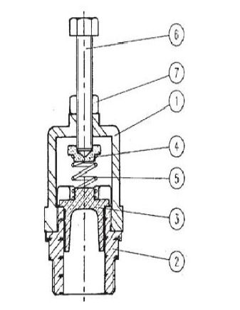
Safety Valve Adjustment
The Root Blower furnished with safety valves is pre-set according to the specified pressure. Before actual running the unit, confirm again if the safety valve setting conforms with the specified releasing pressure, so as to ensure the safety of the motor and the blower. If the blower is to be used at a pressure different from the preset pressure, or if the pressure requirement changes, the releasing pressure of the safety valve must be re-adjusted.
Adjustment Procedures:
Loosen the valve cap
Loosen the fixing nut
Adjust according to the required pressure
For lowering the pressure:TH: Turn the adjusting bolt upward
For increasing the pressure:TH: Turn the adjusting bolt downward
Test if the safety valve releases at the set pressure.
Tighten the fixing nut
Tighten the valve cap
Test again if the valve releases at the correct pressure.
Shaft Seal
Lip Seal is a standard shaft seal for all the Root Blowers produced by the company.
Lubrication
Bottom of the synchronized gear in the gearbox is submerged in the oil, there is also an oil splashing plate for properly lubricating the bearing(s) on the side.
Gear lubrication (Gearbox)
Replacing gear oil (drains the old oil then pour into the new one).
The first time: 100 hours after initiation; afterwards, replace oil every 1000 hours.
Quantity of Oil
Refer to the following table for the oil quantity for each model; check the oil gauge from time to time.
The oil level shall be kept between the upper and lower limits when the unit is in stop. Excessive oil will flow out from the hole on the side. Insufficient oil can result in squeaking of the gear due to friction and shall be made up.
Type of Oil & Grease
Gear Oil CASTROL SAE-90 & Grease CASTROL AP-2/AP-3
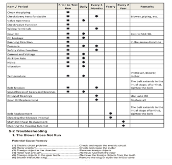
Checking the blower
Daily Inspection
| Inlet/ outlet pressure check | Bearing temperature |
| Gearbox temperature check | Motor current and loading |
| Check for abnormal sound | Oil level confirmation |
Monthly Inspection
Belt tension and wearing,Check the inlet filter for clogging ,Vibration, Check the oil for leakage
Half-Year Inspection
Stop the unit, turn the shaft with hand; ensure the bearing, gear and rotors are all in normal conditions.
Repair and Replacement
Under adequate maintenance, the blower can have a long lifespan. In case of finding any wear and tear of the parts, for the sake of continued normal operation, such parts shall be repaired or replaced.
The Gear
For avoiding collision of rotors inside the blower chamber, provide proper marking for correct resumption when disassembling the gear, so that original angles and positions can be maintained when re-assembled.
Since the synchronous calibration of the gear is quite a difficult process, we suggest Contact ROOTECH ROOTS Blowers Technical Cell.
© 2021 Rootech Service. All Rights Reserved.
Powered By